Control Panel
Connecting & Disconnecting Camera
The first step of using the DaoAI Camera Studio is to connect your cameras.
Connecting
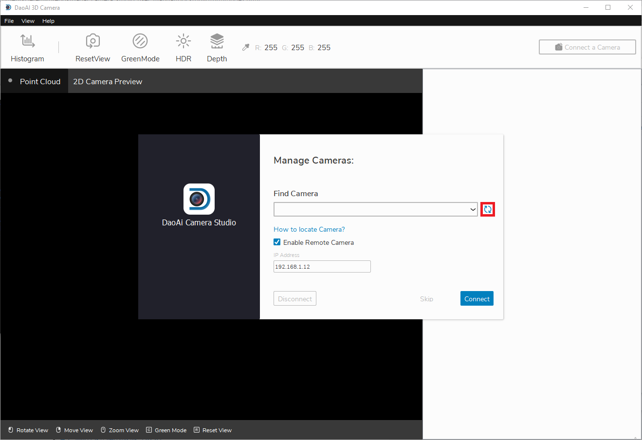
When starting up the Camera Studio, at first you will see the Manage Cameras window.

The refresh button updates the list of connected cameras.
Note
If you are using a remote controlled camera, you will have check the Enable Remote Cameras checkbox and specify the camera’s IP address first before clicking refresh.
- Default IP for Remote Camera
192.168.1.2: BP-L camera, BP-M camera, BP-S camera, BP-AMR-GPU camera, and IN cameras
192.168.1.12: BP-AMR camera
If you still can’t find your camera, check out
Once you detect the camera you wish to connect to, click the Connect button. If there are multiple cameras connected, you can choose which camera to connect to from the dropdown list.
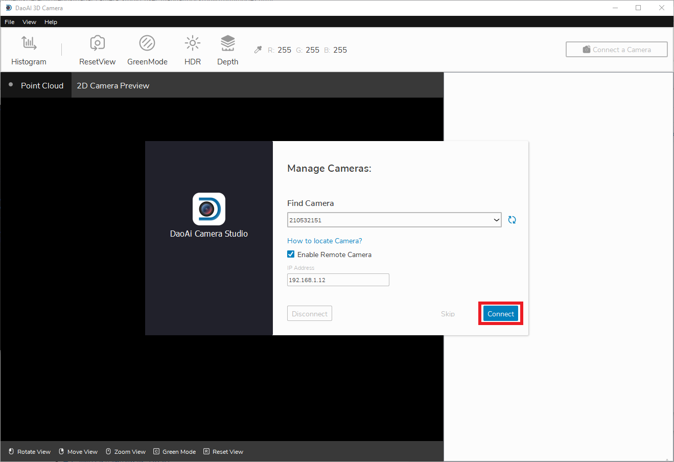
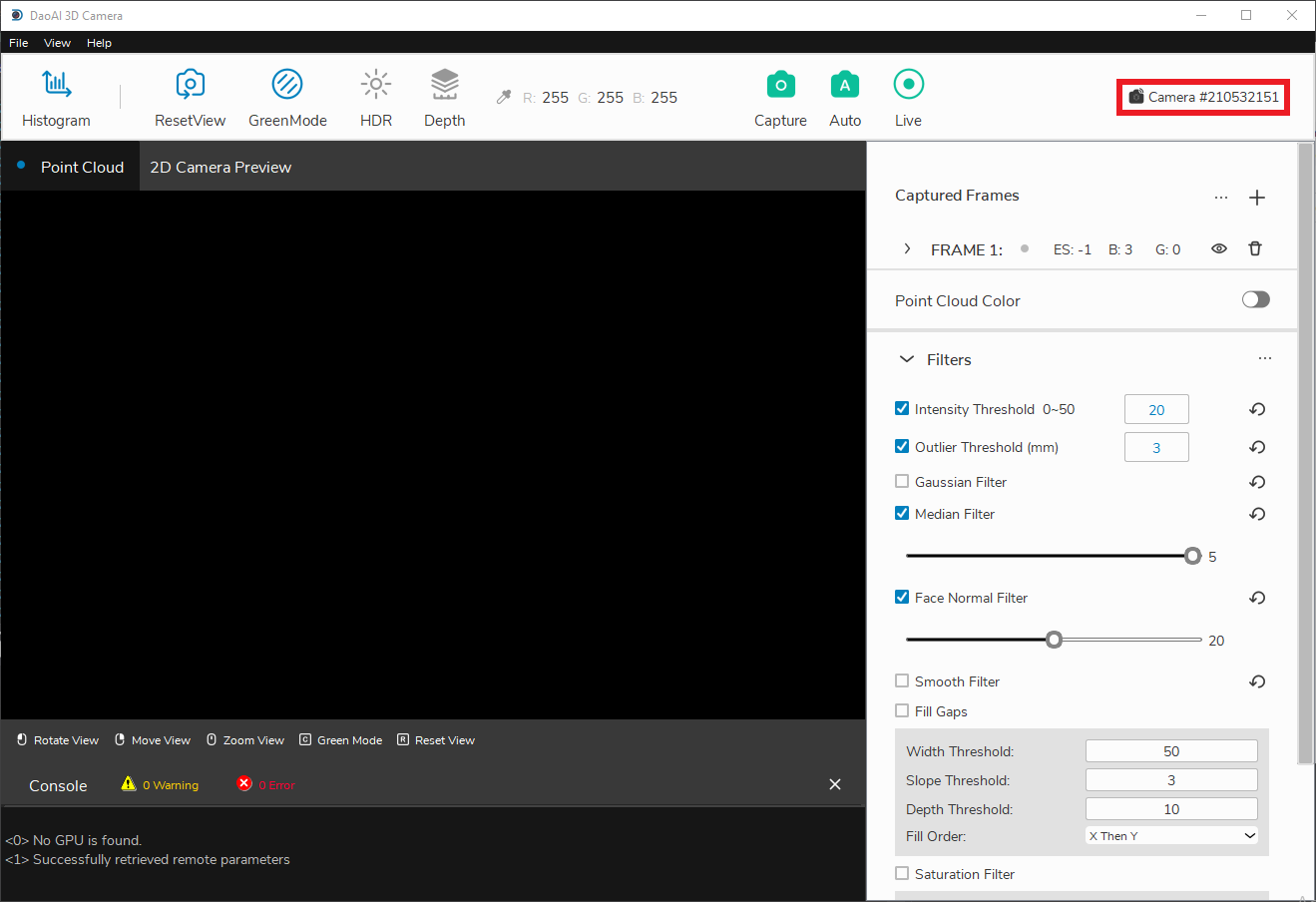
After connecting, you should see the main window.
Note
Normally, if multiple cameras are physically connected, they will all appear in the camera selection list. However, DaoAI Camera Studio only supports establishing a connection with a single camera at a time. To capture with multiple cameras using DaoAI Camera Studio, please start another instance of DaoAI Camera Studio and connect the other camera.
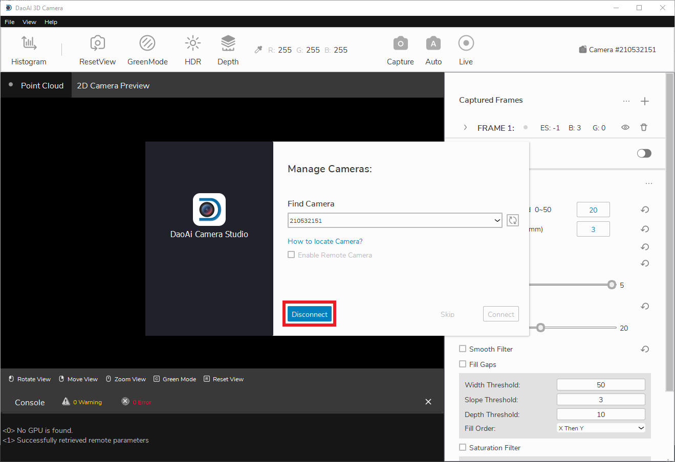
Disconnecting
To disconnect your camera, first click the camera ID in the top right area of the main window.
From there, you should see the Manage Cameras window, where you can click disconnect.
Captures
Performing captures is one of the main features of our Camera Studio software. Camera Studio has 3 capture modes to choose from:
Single Capture
Auto Capture
Live Capture
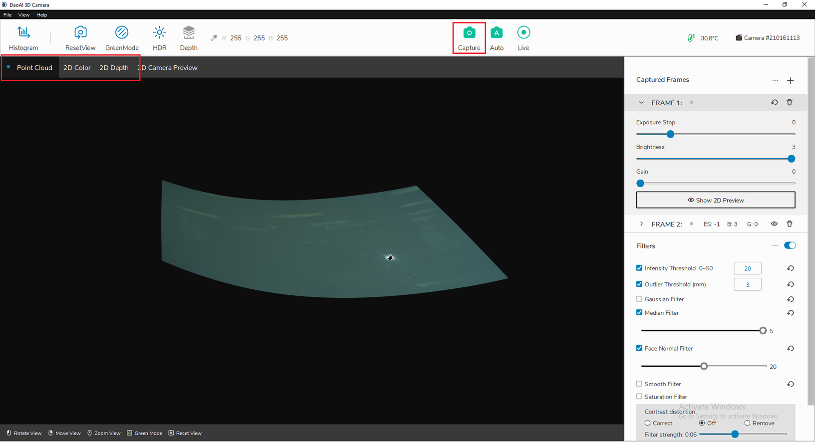
Single Capture
When you click “Capture” on the top bar, the camera will capture images using all the frames and their corresponding settings. For all capture modes, you can view the depth map (Depth), color map (Color), and the point cloud map (Point Cloud) by switching between these tabs.
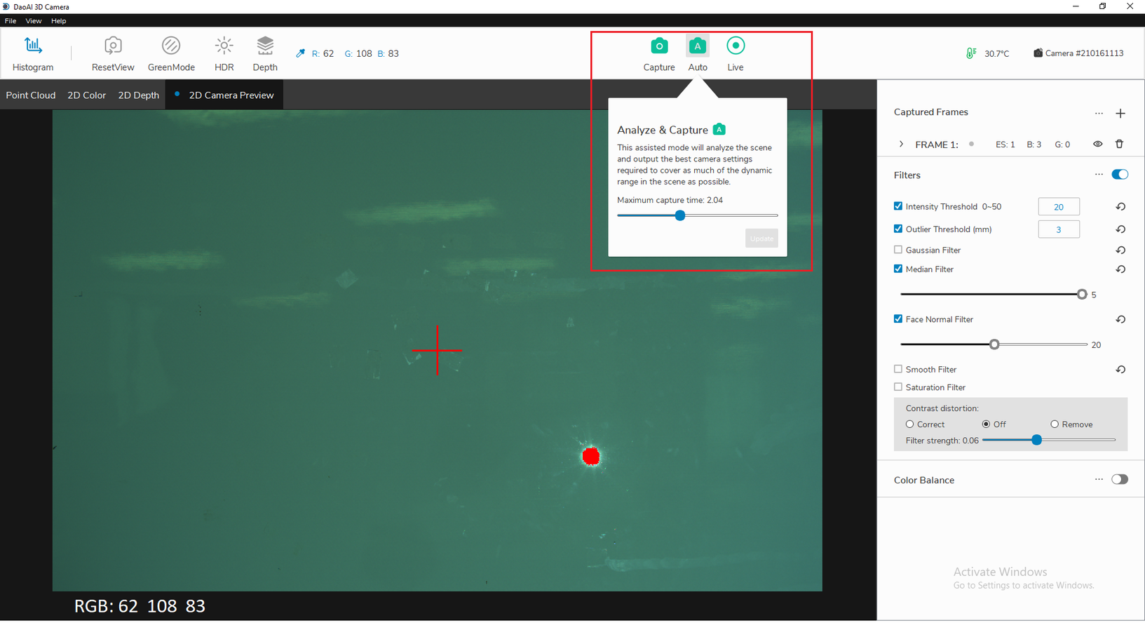
Auto Capture
When you click “Auto”, an analysis of the image environment will be conducted and frames will be automatically generated in order to maximize the dynamic range of the final image. Then, a single capture will follow using the new frame settings. In this mode, you can also specific the Maximum capture time. This setting will change the maximum cumulative exposure time for the frames it can generate based off of the initial analysis.
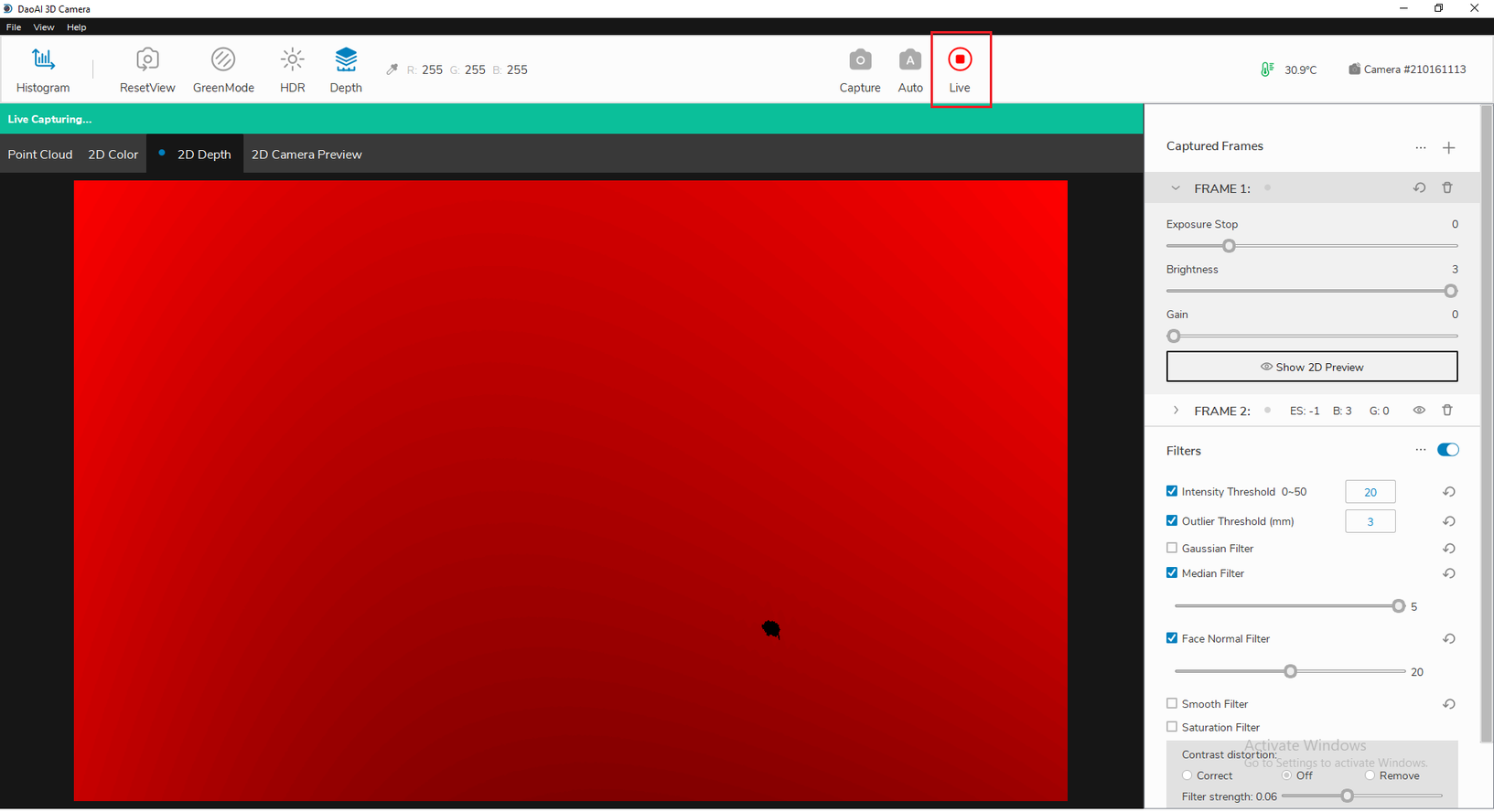
Live Capture
When you click “Live”, Camera Studio will continuously perform single captures. To stop performing captures, simply click the button again (while Live mode is running).
Depth
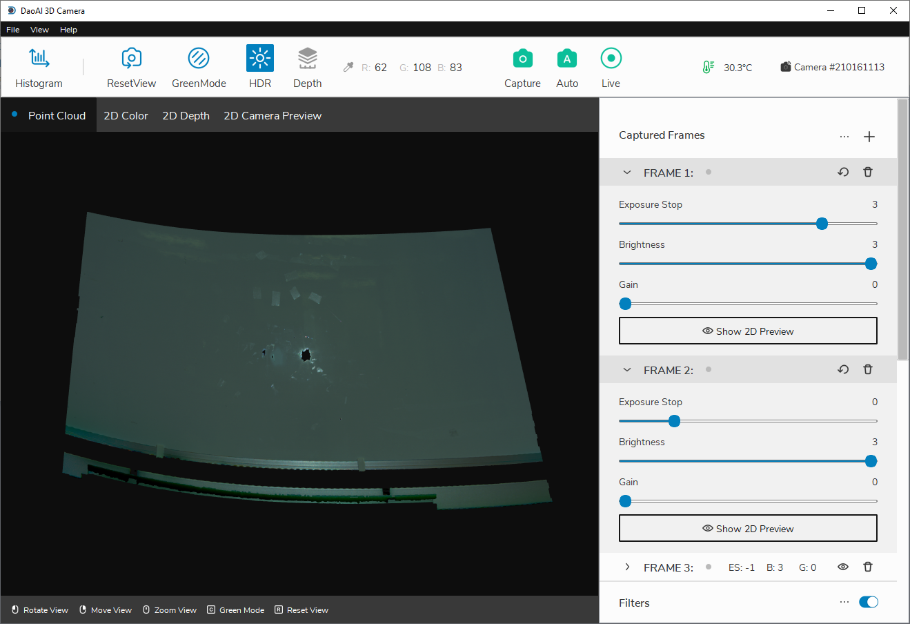
Frames
Frames are used to adjust exposure stop, brightness, and gain levels that are applied when doing captures. Camera Studio allows you to add multiple frames with different settings to capture multiple image groups and fine tune the quality of your resulting images.
Adding Frames
When an image does not meet the expected requirements, you can achieve more precise exposure levels by adding more frames and with different exposure file settings. For example, using two frames set at 2 different exposure values, -1 and 0, to make up for the situation where a single frame -1 is too dark or a single frame 0 is too bright.
Click the “+” button on the right frame settings menu in order to add more frames. Similarly, you can click on the trash can icon to delete a corresponding frame. The minimum number of frames is 1.
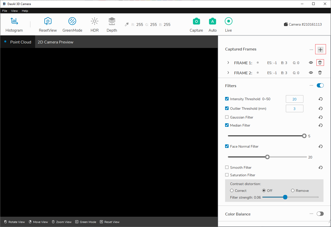
Add and remove buttons
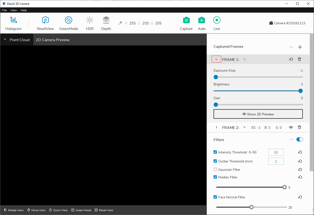
Dropdown menu reveals parameters
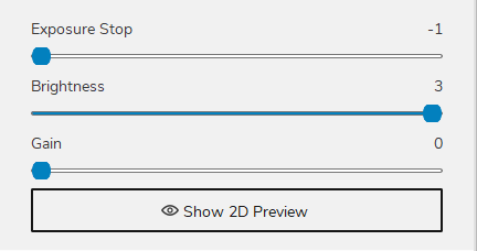
Frame Parameters
All three parameters serves the purpose of adjusting final image brightness and each increase of one in any field will double the final image brightness.
When attempting to increase image brightness, you should prioritize “Brightness”, then “Exposure Stop”, and increase “Gain” last.
Exposure Stop
Responsible for adjusting the exposure time. The level of exposure stops are -1, 0, 1, 2, 3, 4. Since increasing “Exposure Stop” increases capturing time, you should only increase this field when “Brightness” has reached maximum value. The most commonly used exposure levels are -1, 0, and 1.
Brightness
Responsible for adjusting the brightness of the projecter. The possible values are 1, 2, 3. Changing this field does not increase capturing time and should prioritize this field when adjusting image brightness.
Gain
Responsible for increasing the ISO value or sensitivity of the camera. The span ranges from 0, 1, 2, 3, 4 where 0 is the base point 0dB and 4 corresponds to the highest value 24dB (each slider increment causes 6dB change). When the gain is increased or decreased by 6dB, the gain effect is twice as much as that of the previous one. The conversion formula is: 20 x log (gain multiple) = + /-gain dB value. Increasing “Gain” will reduce signal-noise ratio, therefore we should increase this field lastly.
Point Cloud Color
Independently capture the color for Point Cloud.
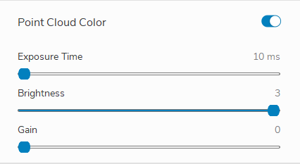
When enabled, a settings section will expand as the image above and when capture, will collect an additional image using the setting for the Point Cloud’s color. The additional image will be captured by projecting a white screen.
The settings are similar to “Frame Parameters” except the “Exposure Time”, which is in miliseconds, allowing more precisive controls.
Filters
This section describes the filters used for pre and post processing images in order to improve the point cloud quality.
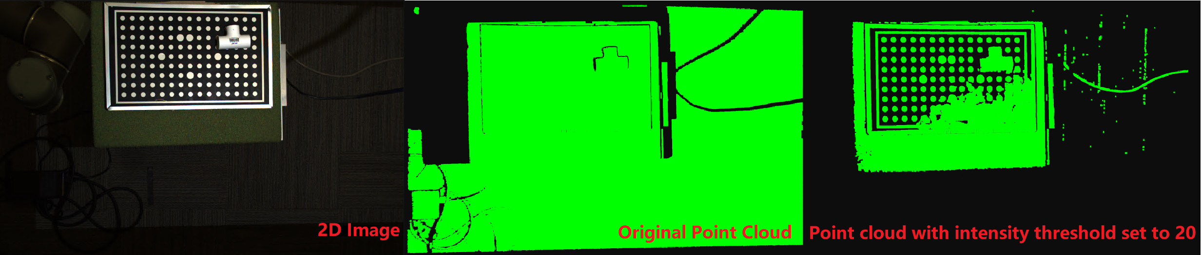
Intensity Threshold

Our intensity metric is based on the average pixel intensity value from the four fringe projections from capture. The threshold helps filter out outliers that are caused by low-quality pixels within dark areas in an image. Generally, we see that for objects with low reflectivity, the algorithm is not able to conduct 3D reconstruction and thus computes incorrect points there. The value of the intensity threshold corresponds to the averaged RGB value we want to filter at.
e.g. When the intensity threshold is 20, all the pixels in the final image with values <= 20 will be filtered out.
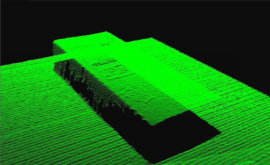
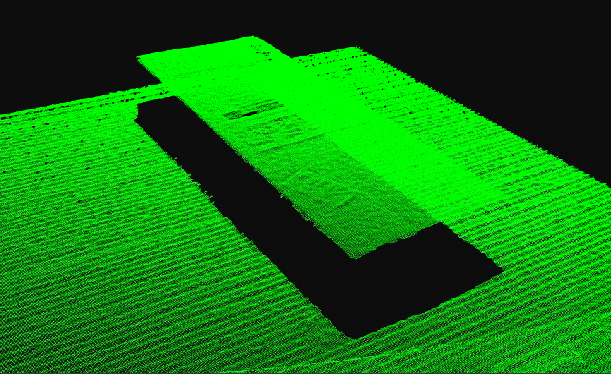
Outlier Threshold

Filter out points which are more than a certain distance from their nearest neighboring point. For example, if set to 3mm, it is determined whether the straightline distance between two adjacent points is greater than 3mm. If it is greater than 3mm, the point is filtered out. However, if there are multiple outliers close to each other, this filter will not be able to filter out those points.
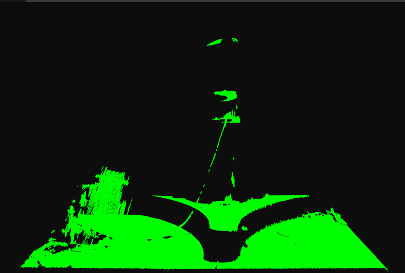
Point cloud without outlier threshold set
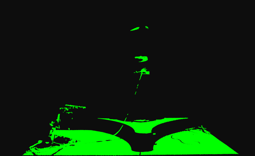
Point cloud with outlier threshold set to 3mm
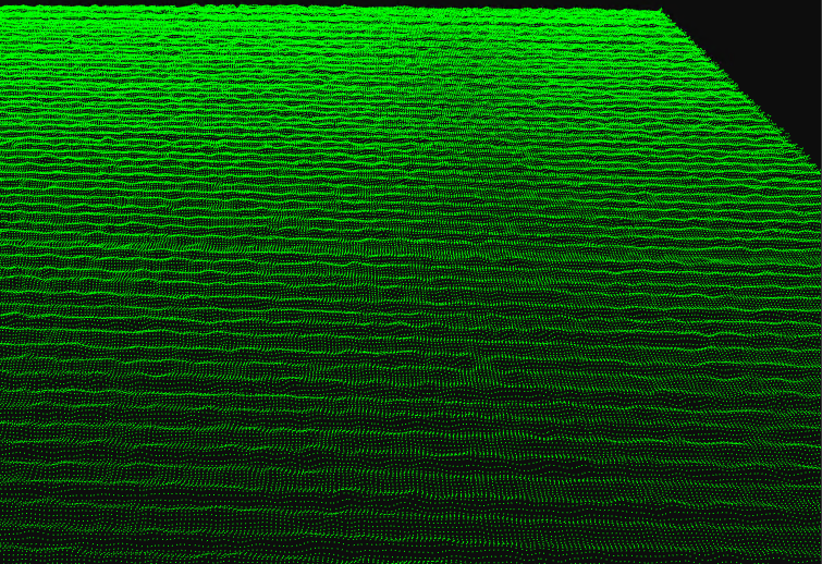
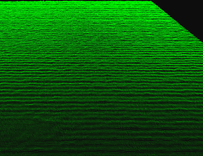
Phase Quality Filter
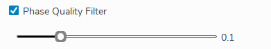
This filter is used to filter out low contrast areas. The track bar can be used to set the filtering strength. Higher value will filter out more areas. For example, using a phase quality filter of 0.3, some area of the floor is filtered out in the point cloud.
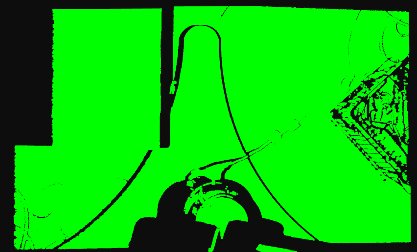
Point cloud without phase quality set
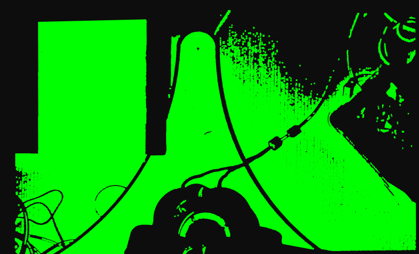
Point cloud with phase_quality set to 0.3
Gaussian Filter
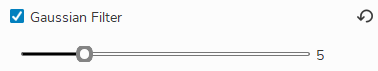
This filter applies a moving average window to each pixel of the captured image. The gaussian kernel size can be set to be 3x3 , 5x5, 7x7, 9x9, 11x11, and 13x13. This applies a smoothing effect on the point cloud and also helps to remove outlier points.
Original point cloud
Point cloud with Gaussian filter of kernel size 5x5
Point cloud with Gaussian filter of kernel size 9x9
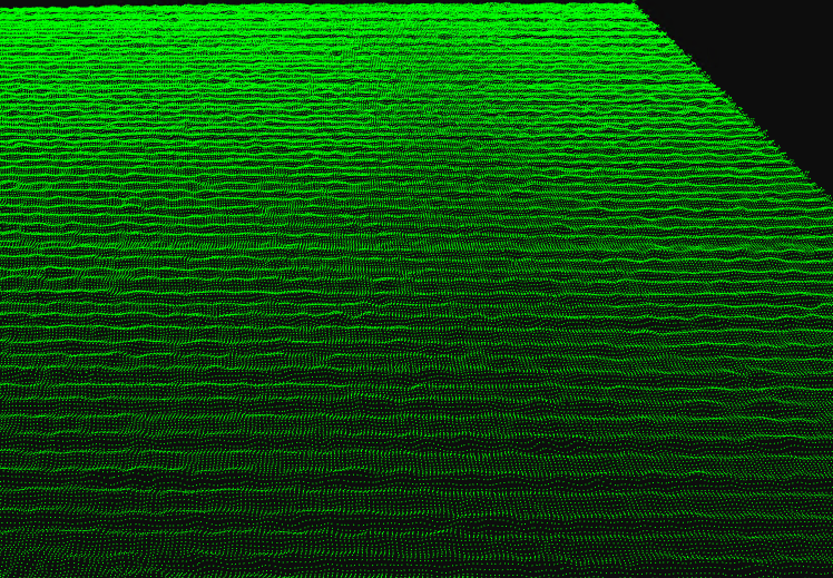
Median Filter
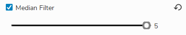
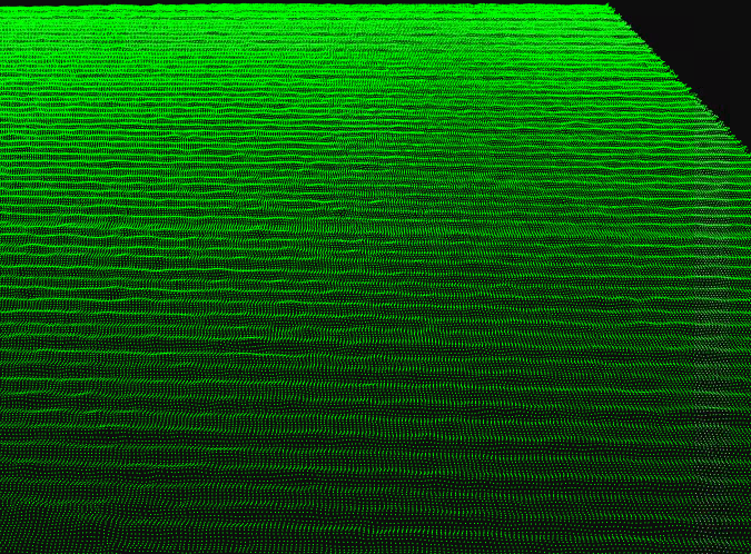
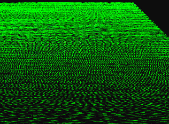
This filter finds the median value of a sliding window to update the current pixel as. The kernel size can be 3x3 or 5x5. This applies a smoothing effect on the point and helps remove outlier points.
Original point cloud
Point cloud with median filter of kernel size 5x5
Face Normal Filter

This filter analyzes a point cloud polygon mesh to find the surface normal vector of any polygon. If the surface normal vector is at an angle larger than the face normal value with respect to the line of sight, then the points are filtered out. On objects with sharp corners and large areas where the surface normal is perpendicular to the line of sight, many outliers occur. An example is a box: the walls sometimes create outlier points in the point cloud due to noise, low contrast or over-saturated images.
Without this filter, the incorrect points show up on the edges of holes, sharp drop offs, vertical faces, and more.
Original point cloud
Point cloud with Face Normal Filter
Remove Small Area
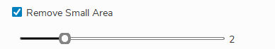
This filter removes small chunks of isolated point cloud. Since noise often appear in the form of small dots, they can be removed using this filter.
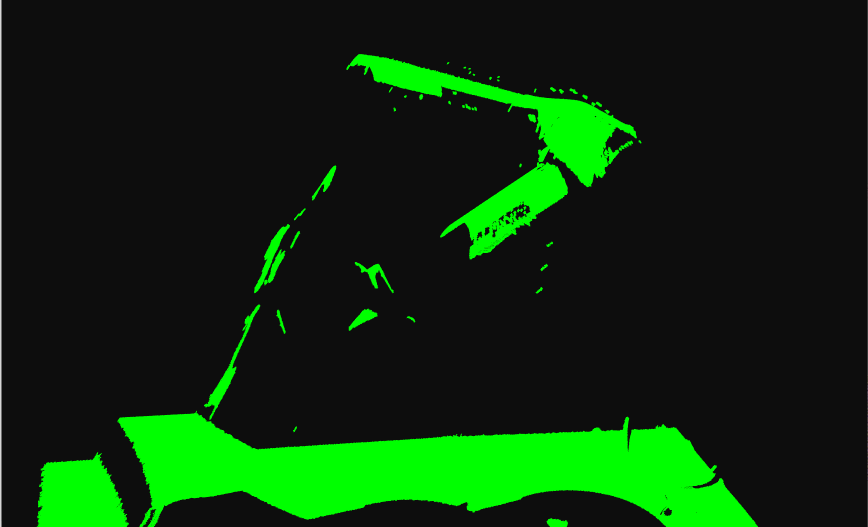
Original point cloud
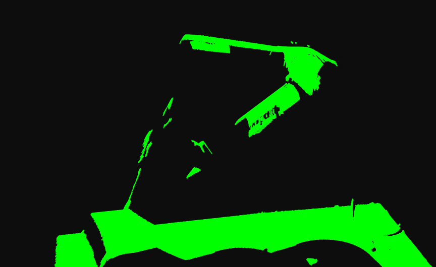
Point cloud with Remove Small Area
Smooth Filter
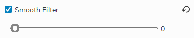
This filter is a post-processing filter which rounds the depth value of an organized point cloud to the nearest mm. For example, if the smooth value is 0.5, each of the depth values will be rounded to the nearest 0.5mm. This filter is useful in scenarios where images with noise errors causes small oscillations on the point cloud. If you know the model is flat and you see small oscillations in the point cloud, you can use this filter to round the data to create a flat model.
Original point cloud
Point cloud with Smooth Filter
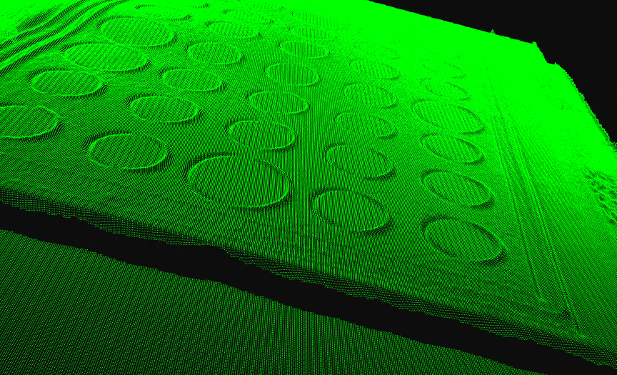
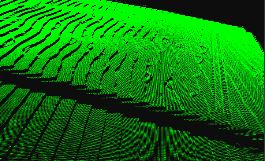
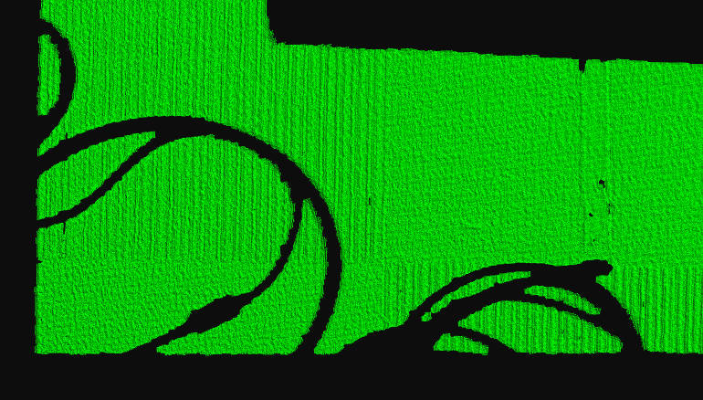
Fill Gaps
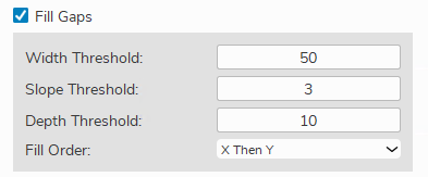
Interpolation can be used to caltulate the coordinates of points in areas where points are missing from the point cloud. There will be scenarios where your point cloud is missing points in areas due things like reflection, poor lighting, etc. Thresholds can be set for maximum gap area width, depth, and slope, to describe the areas of the point cloud where interpolation will occur to calculate and fill in these missing points.
Original point cloud
Point cloud with Fill Gaps
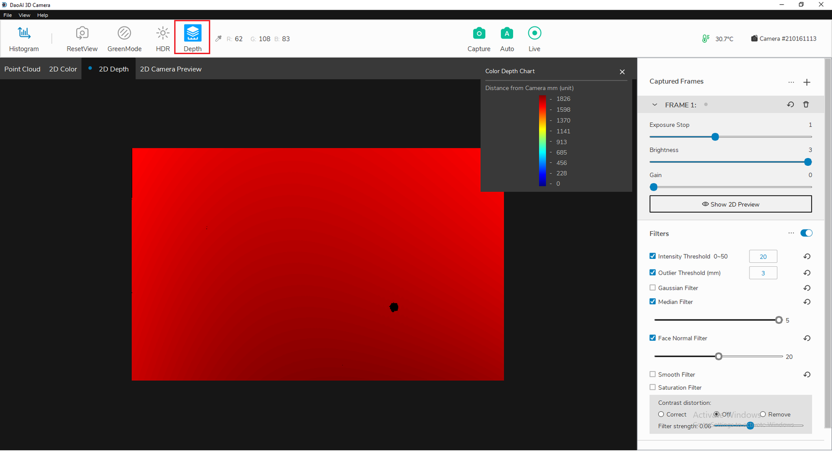
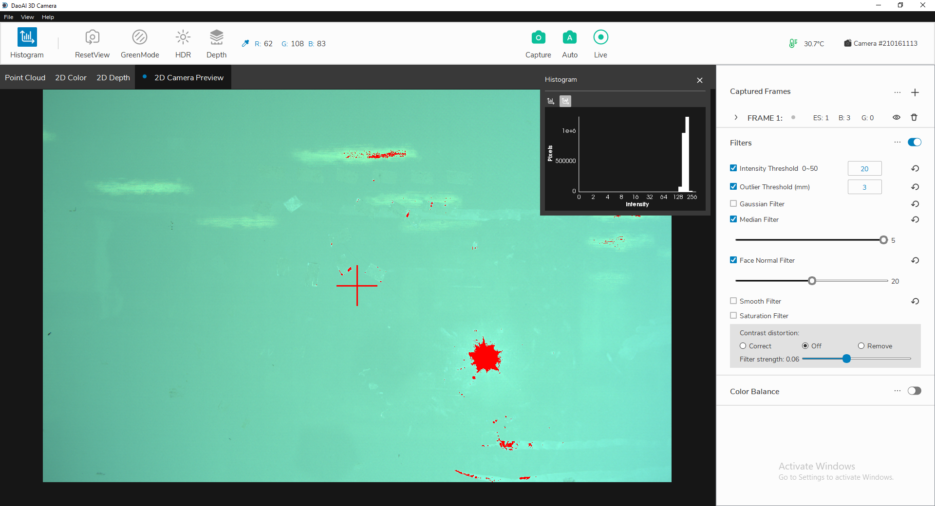
Saturation Filter

This filter removes areas that are overexposed. When one of the three RGB channels exceeds 255, it deletes the pixel. Usually G (green) is the first overexposed channel. When using the filter, HDR mode is automatically selected and can be manually cancelled if it is not necessary.
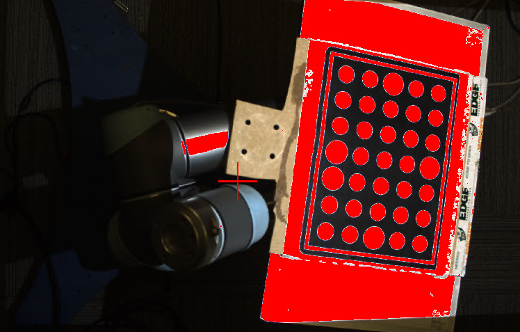
Area in red marks the over-saturated area
Point cloud with saturation filter
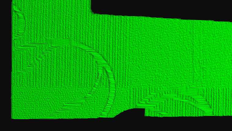
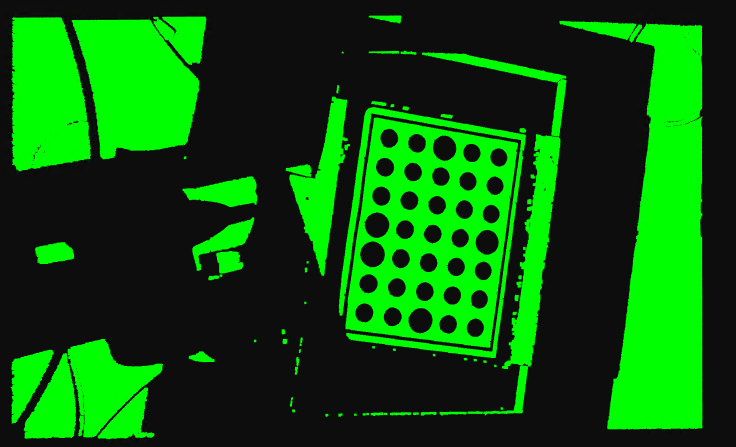
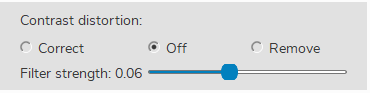
Contrast Distortion Filter
Contrast distortion occurs due to imperfections in the lens and optical phenomena like diffraction and chromatic aberration. It appears when there is an abrupt contrast change from a highly absorptive to a reflective surface (e.g. in a black to white transition on a checkerboard), which leads to measurement errors in the 3D point cloud.
If “Remove“ is selected, regions of high contrast distortion will be removed from the 3D point cloud.
If “Correct“ is selected, measurement errors caused by contrast distortion will be compensated based on a “Strength“ value user set on the GUI. The higher “Strength“ value user use, the more measurement error will be compensated. Note that, it’s possible to over-compensate the measurement error which looks like “opposite“ contrast distortion.
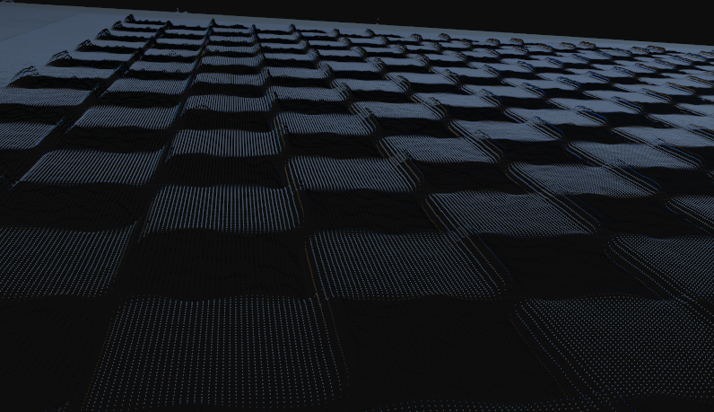
Point cloud color image (contrast distortion visible)
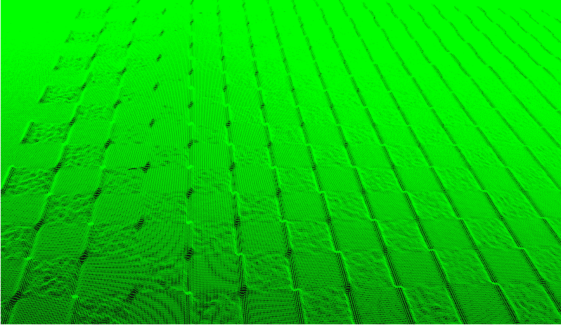
Point cloud green image (contrast distortion visible)
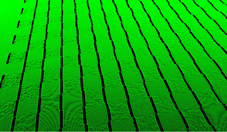
Using “remove” for contrast distortion
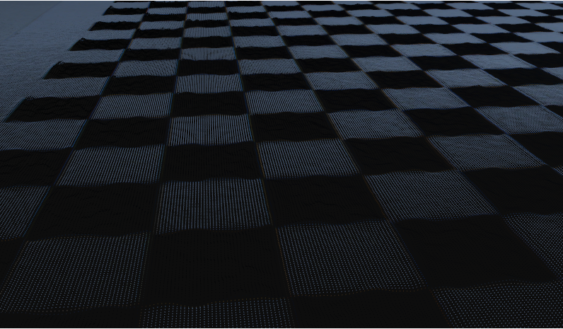
Using “correct” for contrast distortion
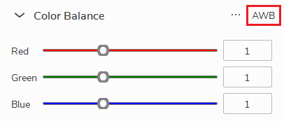
Color Balance
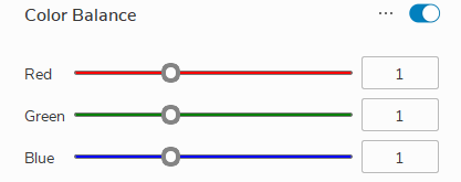
Color balance controls
By increasing the corresponding value of R/G/B, you can make the image closer to that color. The default value is 1, the minimum is 0.5, and the maximum is 2.
Used when the color of the background environment is slightly inclined to a certain hue. Adjust the balance of other colors. Usually, it does not need to be set up.
Preview options are not available, a single capture is required to see the image effect.
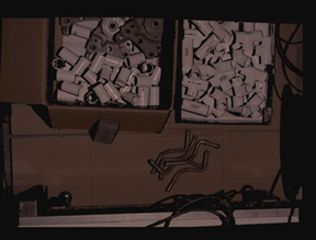
R biased color balance
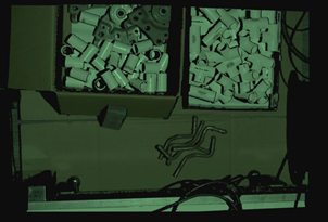
G biased color balance
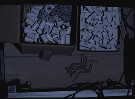
B biased color balance
Clicking the “AWB” (as the image above) to use the auto white balance tool. After clicking the “AWB”, drag to select an area of neutral color (white or gray) and click confirm. R, G, B values will be computed so that after applying color balance, the selected area can be adjusted to white.
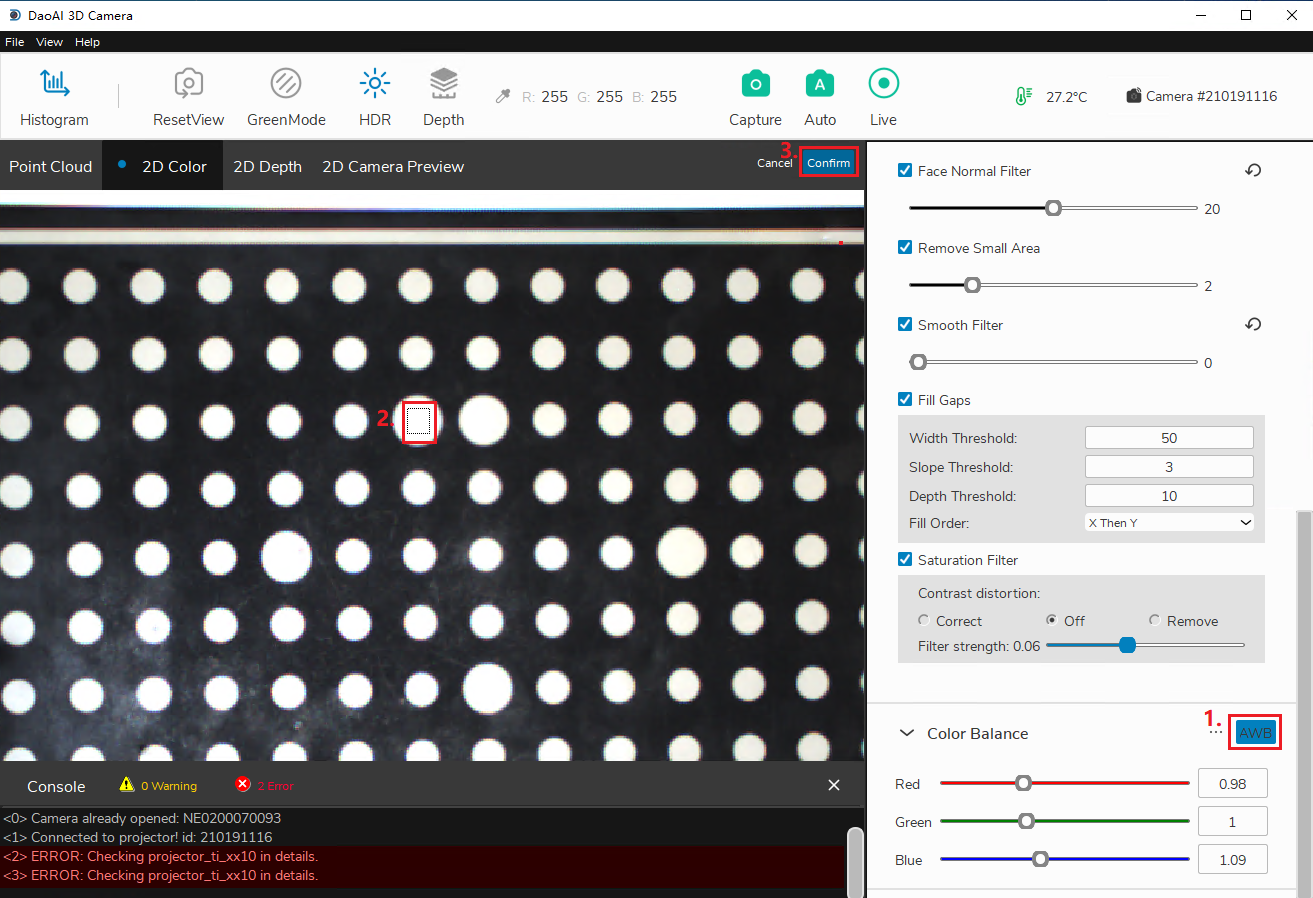
drag and select an area in the display
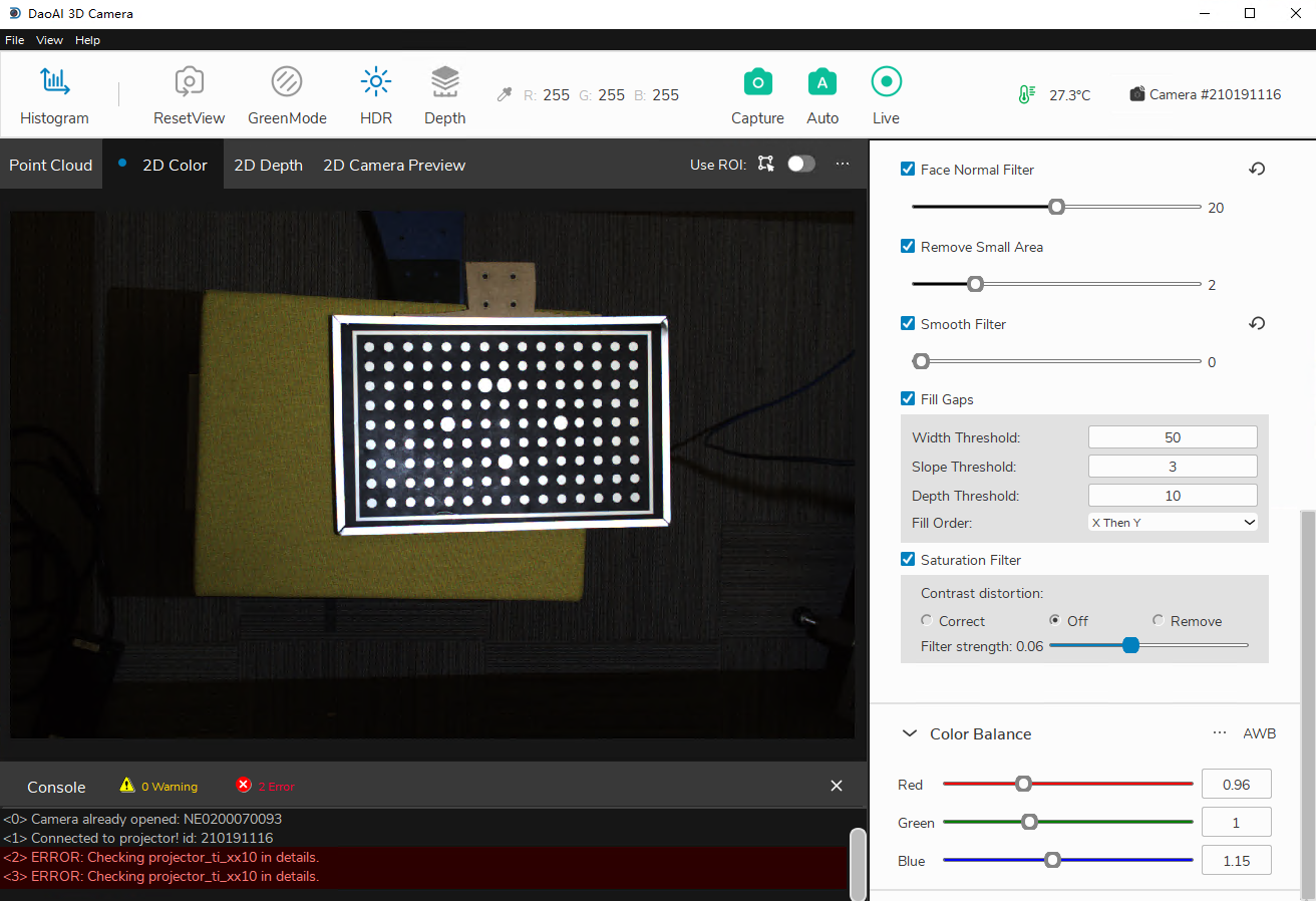
image after auto white balance
Green Mode
The Green Mode switches between RGB point clouds and green point clouds display.
RGB point clouds
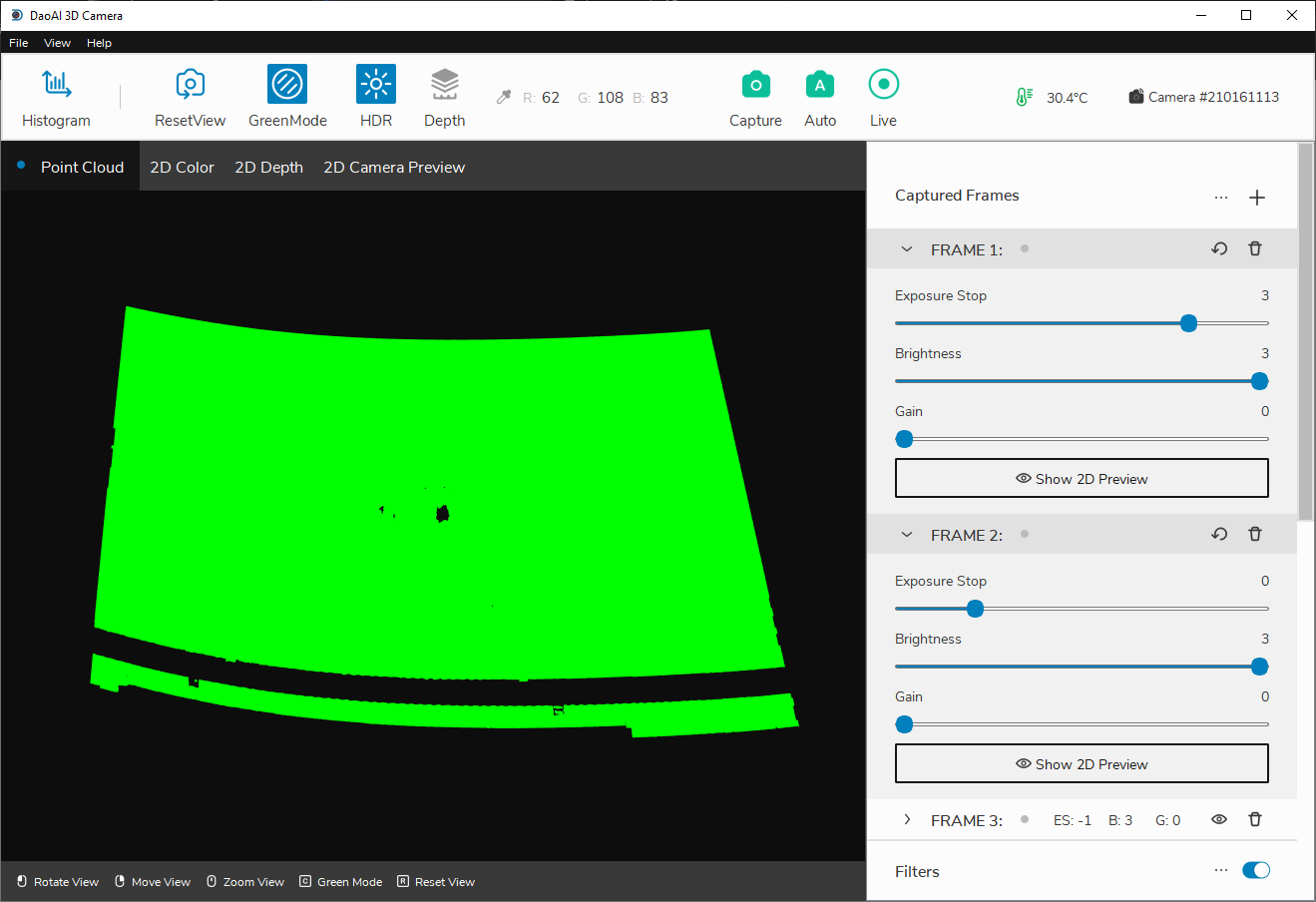
Green Mode point clouds
HDR
Below are the same colour image with HDR off and HDR on respectively:
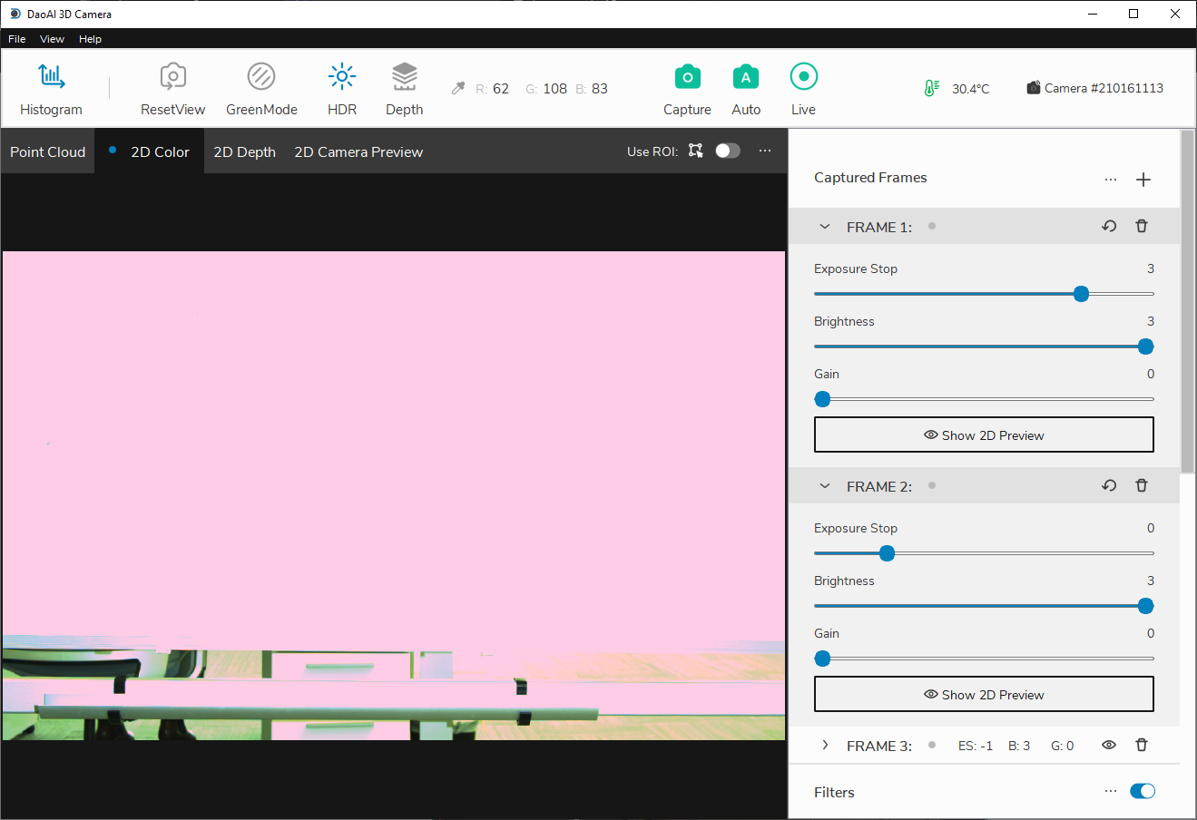
Colour map with HDR off
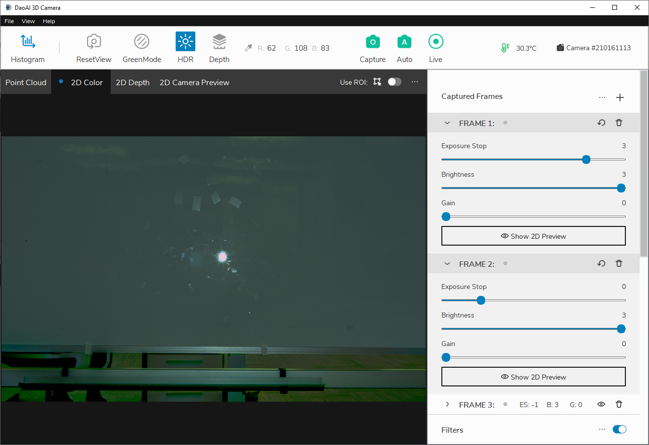
Colour map with HDR on
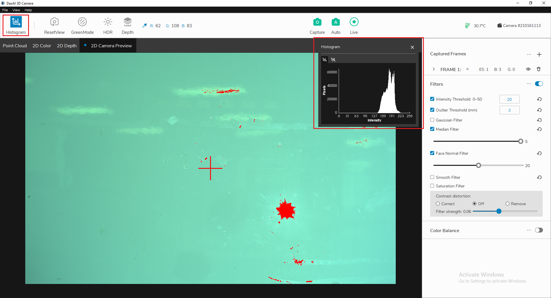
Histograms
The histogram window provides a visualization of the distribution of the RGB values (0-255) of all the pixels in the image.
Goal: To have the highest column in the logarithmic histogram to around 128 to avoid 255 overexposures. This can be achieved by adding frames and adjusting exposure levels.
Click “Histogram” in the upper left corner to toggle the histogram window. The histogram plot will pop up on the screen automatically. Inside this window, there are two different tabs for switching between graphs of a linear distribution and logarithmic distribution. Overexposed pixels are marked a red color so you can easily see them. If there are a large number of pixels in 255 range, the image is overexposed. Shorter exposure time or lower brightness should be chosen to limit the overexposure.
Linear distribution
Logarithmic distribution
Logarithmic distribution can help adjusting the brightness to desired range.
For example, as the image below, we want to adjust the peak brightness from “16-32” to “128-256”.
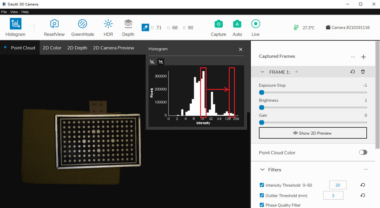
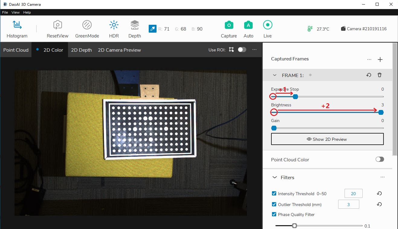
Recall that for frame parameters, an increase of one in any field will double the brightness of the final image, and the ranges in logarithmic distribution also doubles.
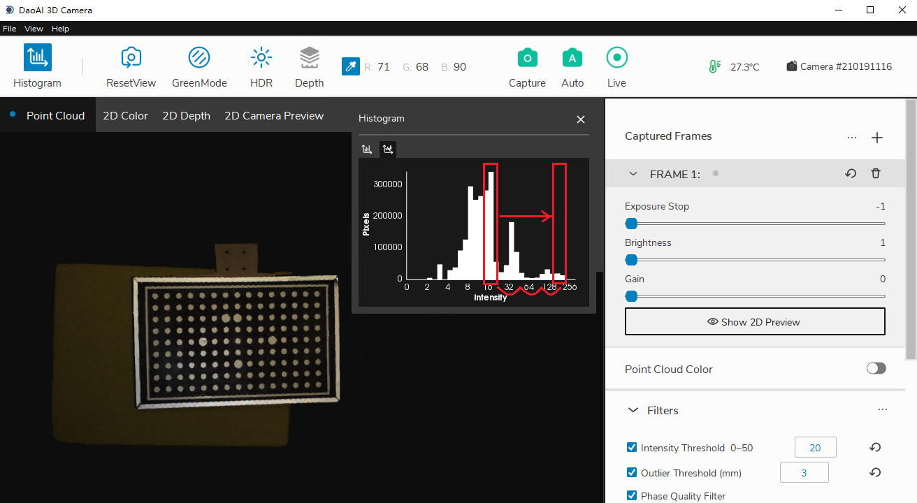
Obeserve that there are 3 intervals from range “16-32” to “128-255”. Then adding 3 to frame parameters can move the peak brightness to our desired range.
Temperature Regulation
If a temperature sensor is available in your 3D system, the system will display the corresponding temperature in the top right corner of the main menu. By default, if the temperature sensor is available, a temperature control system will be enabled.
Modes There are two modes for temperature control: normal and regulating
Normal: This is the regular mode in which all software features are enabled including captures, 2D previewing, etc. While the temperature control status is normal, the temperature icon in the main window will appear green.
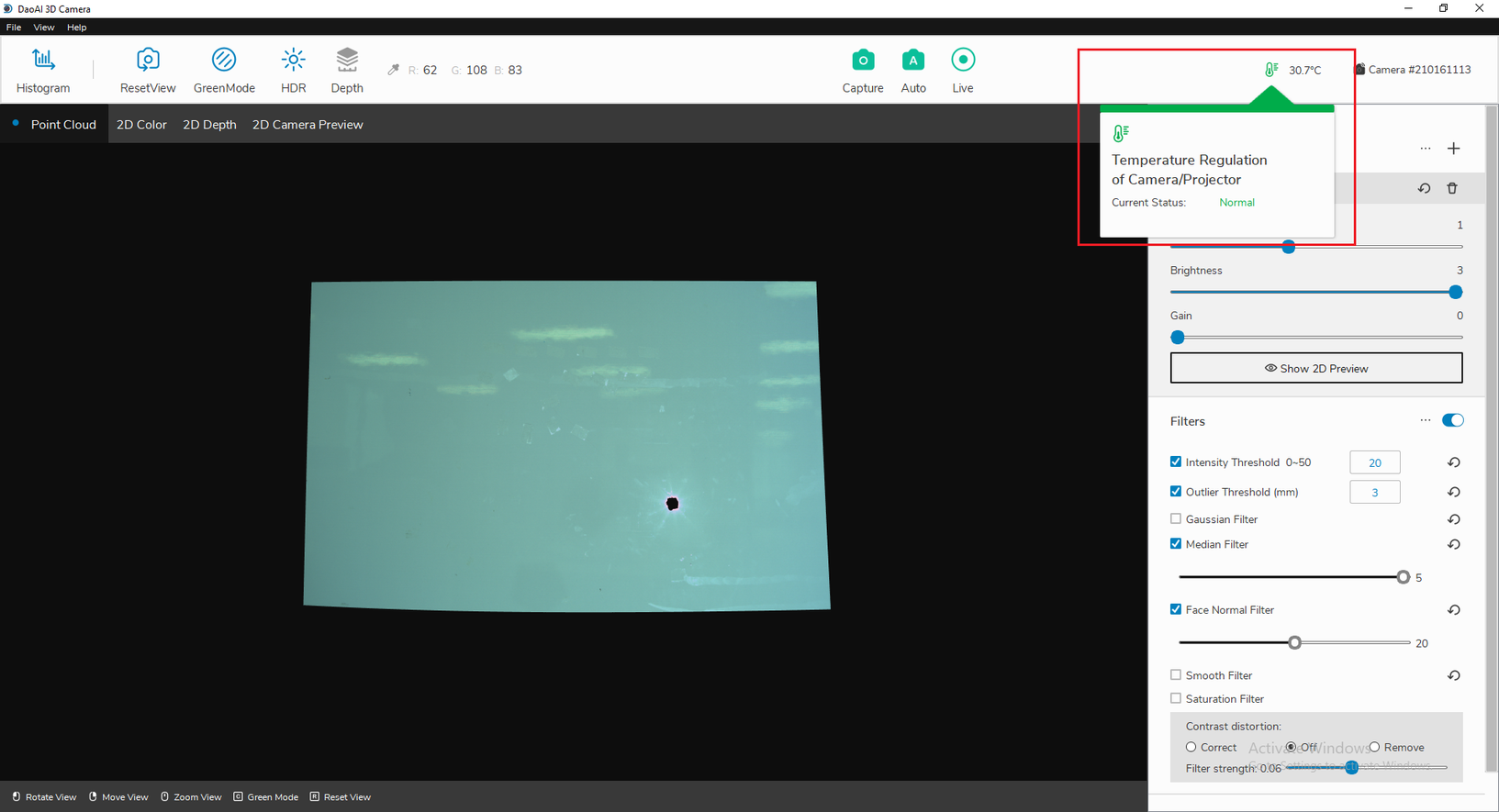
Temperature icon is green
Regulating: By default, temperature regulation will be triggered if system temperature is above 70 degree Celsius. In this mode, the temperature of the system is abnormal and the main capture features (Auto, Live, Capture, Preview) are disabled in order for the system to regulate the temperature. When in this mode, a temperature control algorithm will be run in order to normalize the system again. While the temperature control status is regulating, the temperature icon in the main window will appear red.
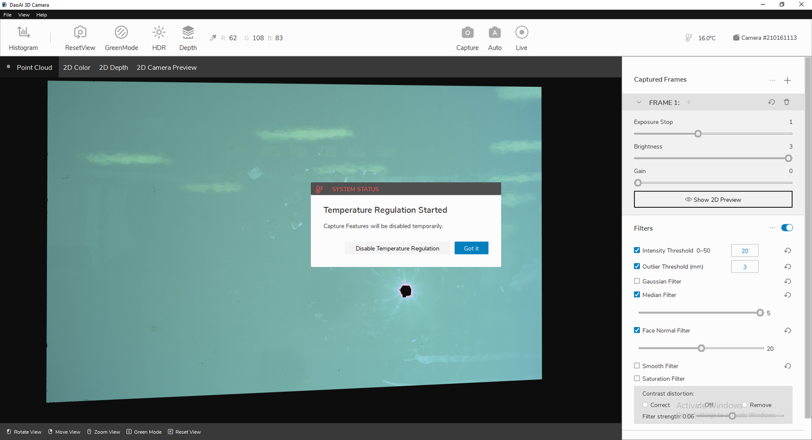
Notification that temperature regulation has started
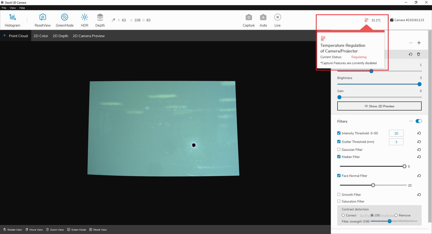
Temperature icon is red
While Camera Studio is regulating temperature, some functionality is disabled in order for the temperature regulating feature to work effectively. You will have to wait for the temperature to be regulated to a suitable level, or disable the temperature regulation feature before you can use these functionalities are re-enabled.
Disable Temperature Control
When camera’s temperature sensor is malfunctioning, you can disable the temperature control to allow normal usage of Camera Studio.
You can click “Disable Temperature Regulation” when the warning dialgue is prompted to disable Temperature Control.
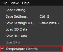
Or you can disable Temperature Control from the menu bar: Click on “files -> temperature control” and uncheck it to disable.