Mechanical Installation
Mechanical interface
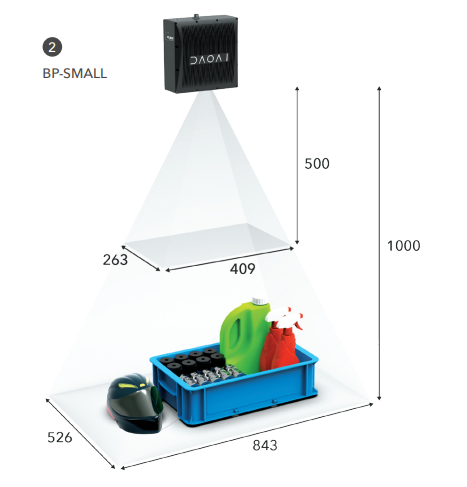
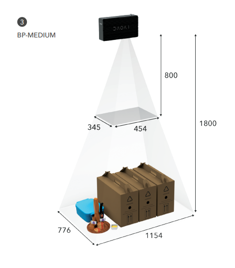
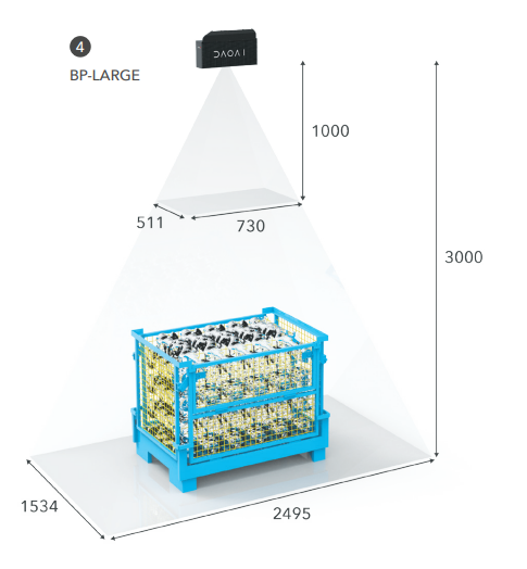
Dimensions
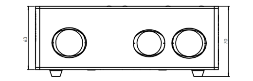
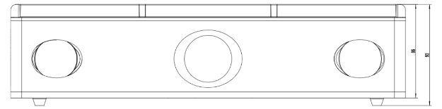
Mounting Specifications
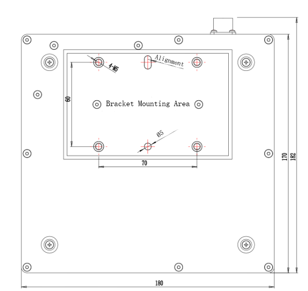
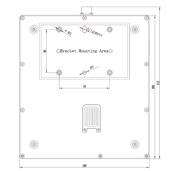
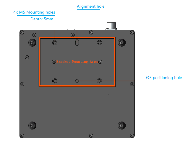
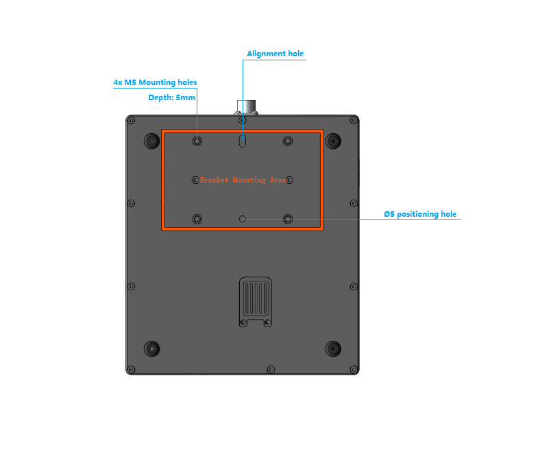
The DaoAI BP SMALL camera has four M5 mounting holes, one Ø5 positioning hole, and one obround alignment hole. To ensure not to damage the threads, we recommend not exceeding the specified maximum torque value when fastening the screws.
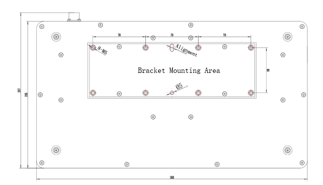
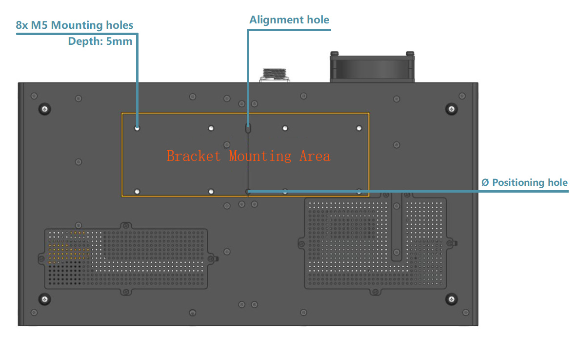
The DaoAI BP MEDIUM camera has eight M5 mounting holes, one Ø5 positioning hole, and one obround alignment hole. To ensure not to damage the threads, we recommend not exceeding the specified maximum torque value when fastening the screws.
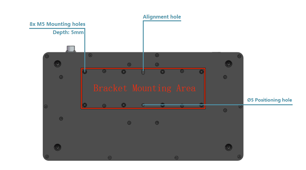
The DaoAI BP LARGE camera has eight M5 mounting holes, one Ø5 positioning hole, and one obround alignment hole. To ensure not to damage the threads, we recommend not exceeding the specified maximum torque value when fastening the screws.
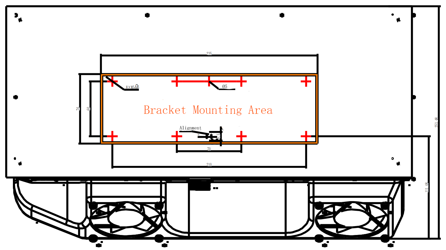
The DaoAI BP AMR camera has four M5 mounting holes, one Ø5 positioning hole, and one obround alignment hole. To ensure not to damage the threads, we recommend not exceeding the specified maximum torque value when fastening the screws.
The DaoAI BP AMR-GPU camera has four M5 mounting holes, one Ø5 positioning hole, and one obround alignment hole. To ensure not to damage the threads, we recommend not exceeding the specified maximum torque value when fastening the screws.
The DaoAI BP LASER camera has eight M5 mounting holes, one Ø5 positioning hole, and one obround alignment hole. To ensure not to damage the threads, we recommend not exceeding the specified maximum torque value when fastening the screws.
Positioning Correctly
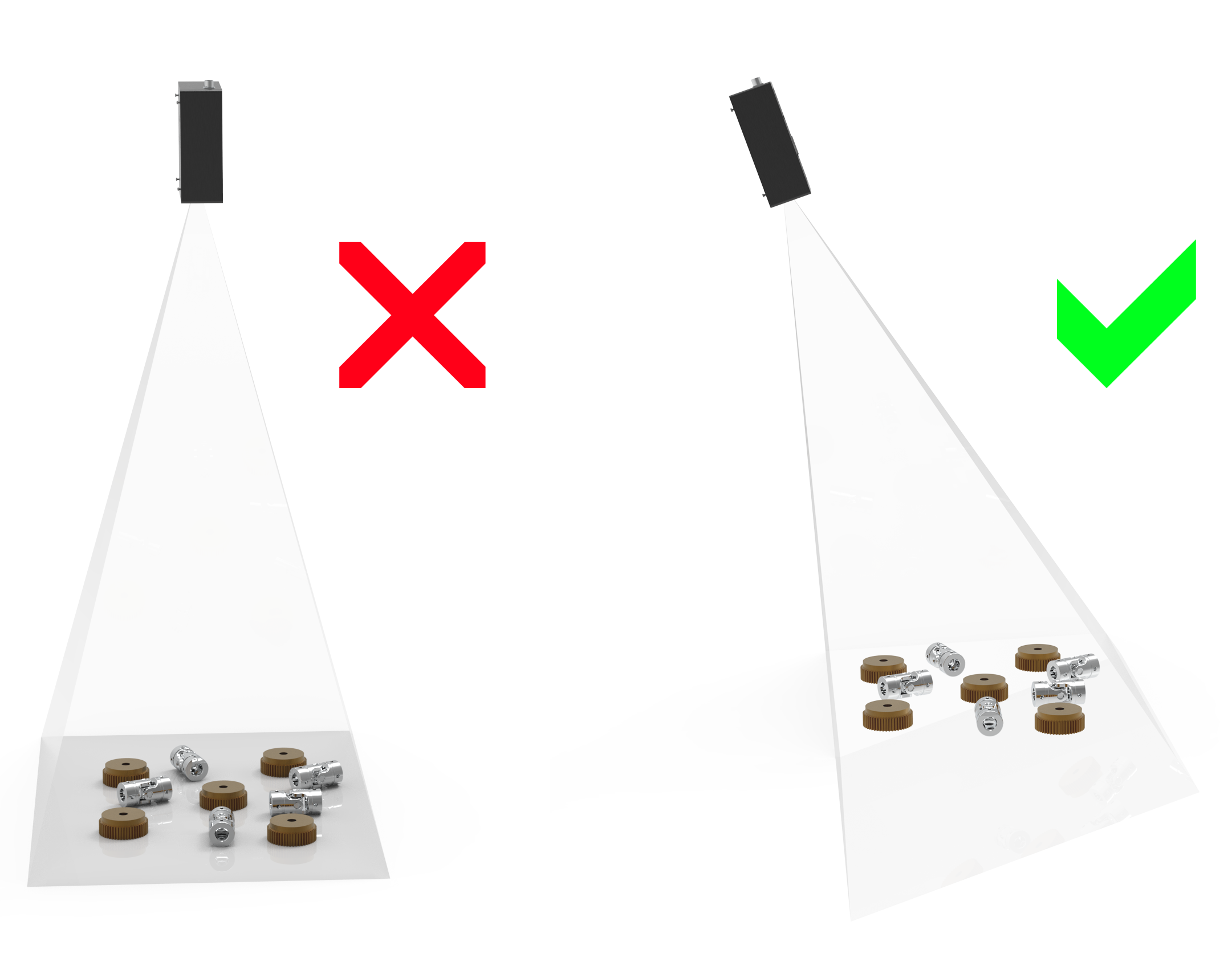
The camera and the projector have an angle with respect to the center axis. This should be considered if it is desired to have the camera perpendicular to the scene.
If possible, mount the camera at a slight tilt angle to avoid reflections and interference from the background. This also frees up space above the scene for easier access for tools and robots. Check out available DaoAI mounts.
Ambient light might reduce performance. Consider blocking direct light affecting the scene.
Note
Camera tilting is more important if the scene contains specular surfaces.
Please checkout Working Distance and Field-of-View Working Distance and Camera Positioning for more information on how to correctly position your camera.
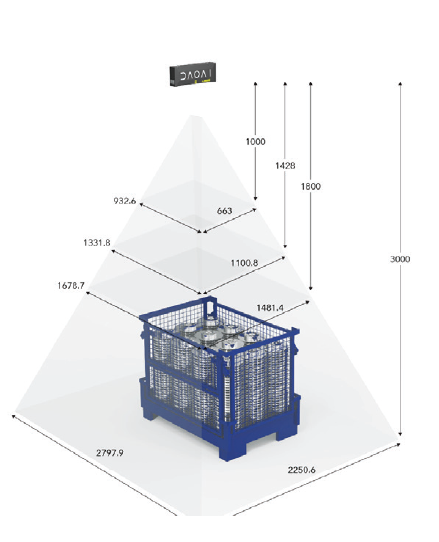
In bin-picking applications
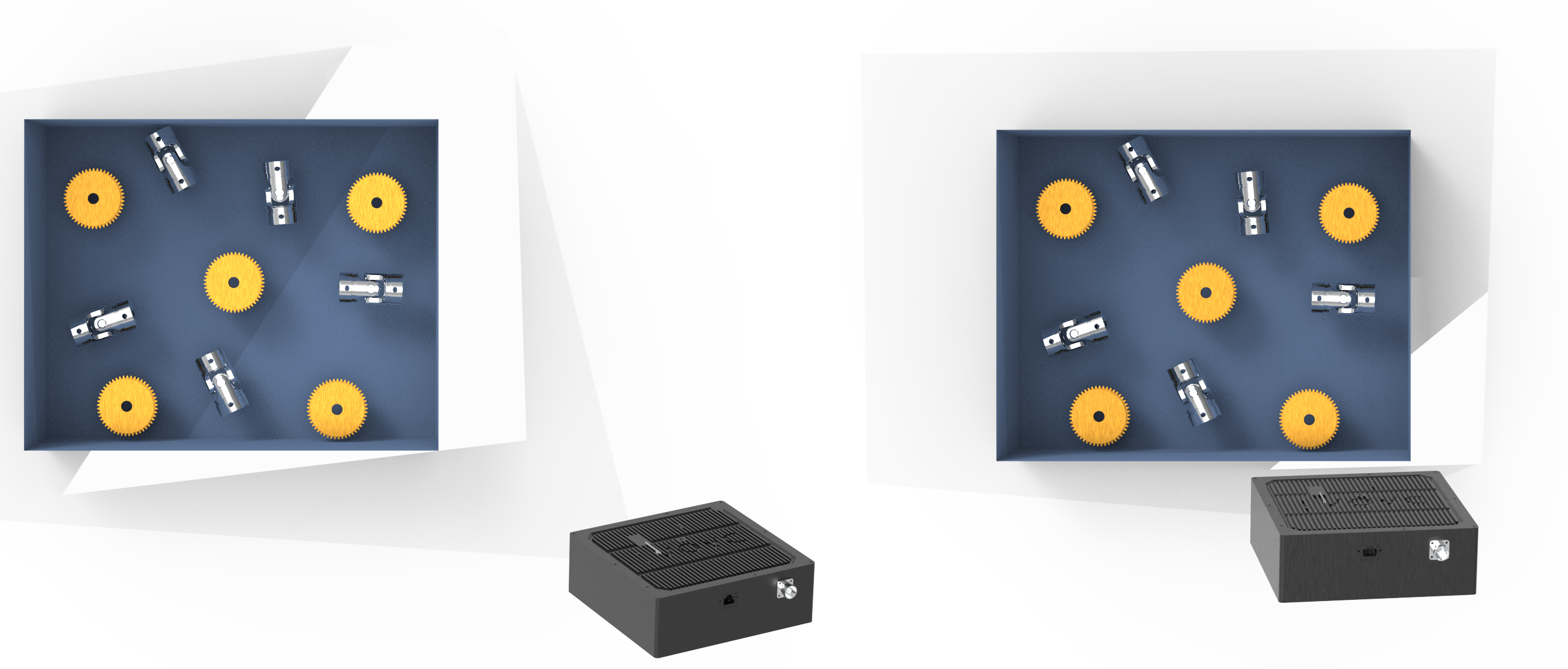
For bin-picking applications, place the DaoAI BP camera projector above the back edge or above the rear corner of the bin (see images below). Pan and tilt it so that the 2D camera is looking at the center of the bin. The projector rays should not fall on the inner surfaces of the two walls closest to the projector; they should almost be parallel to those two walls. Mounting the camera this way minimizes inter reflections from the bin walls.
Cooling clearance
DaoAI BP LARGE cameras use active and passive cooling, other BP cameras use passive cooling, they all allow some space around the device for airflow, and do not block the air opening on its front and rear sides. See the datasheets for the operating temperature range for your camera.
Signal protection
Do not install DaoAI BP cameras and cables next to high voltage devices that can generate high levels of electromagnetic disturbance. Do not route camera cabling through the same trunks/conduits with AC power cables and cables emitting high levels of disturbance.
Continue reading about Connectivity and Power Supply.
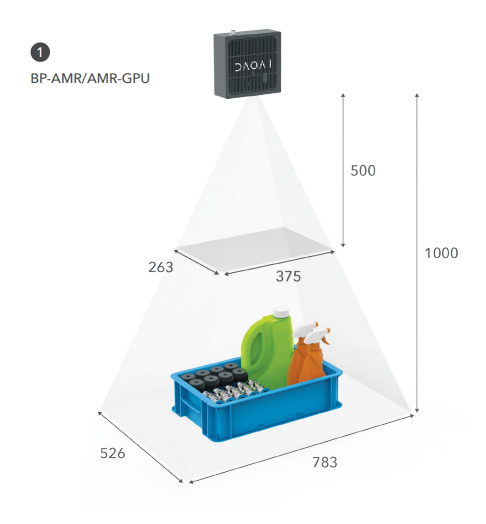
Working Distance and Field-of-View
This series has five bin-picking camera models for various workspace sizes and applications such as bin picking, palletizing, and part loading.
BP ARM/AMR-GPU
BP SMALL
BP MEDIUM
BP LARGE
BP LASER